
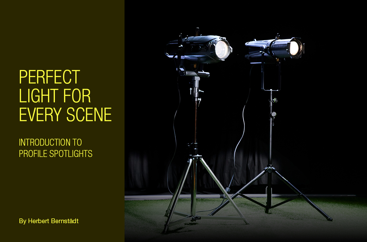
Perfect light for every Scene: introduction to profile spotlights – Part 1
Light is much more than just brightness – it shapes spaces, directs the gaze of the audience, and creates impressive atmospheres. Profile spotlights in particular play a key role in professional lighting technology, as they facilitate precise lighting design with sharp edges, creative projections, and targeted focussing. Whether in the theatre, on stage, or at live events, their wide range of uses makes them an indispensable tool for lighting designers. In this four-part blog series, we will take a deep dive into the world of profile spotlights. We will explain fundamental optical concepts, present various tube and zoom technologies, demonstrate the creative potential of gobos, shutter blades, and irises and compare moving head and static profilers. Let’s start with the basics: what makes a profile spotlight so special and why it is considered the “scalpel of lighting”? In Part 1, you will learn how optical principles work and how a razor-sharp projection is created.
What is a profile spotlight?
When we talk about profile spotlights, we automatically think of theatre scenes and perfectly staged lighting. And that’s for good reason, as we will soon find out.


A profile spotlight is the “scalpel” among spotlights. After all, creating a “hard edge” with light and producing a graphical optical blackout (GOBO) image is only possible with a profile spotlight. How, then, do you produce such an image or hard edge of light? To do this, we need a lens for imaging. If you want to enlarge an image, the image must be placed between the single and double focal length of the lens. We also call this position the “imaging plane”. Functions such as the iris, shutter blade, or gobo are then located on the imaging plane. Magnification is then determined by the distance between the lens and imaging plane. If the position of the spotlight in relation to the surface on which the image is projected is fixed, adjusting the position of the lens will bring the image into focus or make it blurry. The lens remains symmetric when rotated and, as shown in the schematic diagram below, produces both an inverted and upside-down image.
A – image, for example, gobo
B – projected image
C – lens
f – focal point
Imaging plane with distance between f and 2f. The further away the image is projected, the larger it becomes.
If you want to know exactly:
We distinguish a profile spotlight as having two optical tasks. Its first task is to ensure the imaging plane is uniformly flooded with light. Let’s call a spade a spade and refer to this as “primary optics”. The primary optics in a conventional spotlight are located in the lamp housing on the light source. The primary optics must direct as much light as possible along the optical axis to flood the imaging plane with light and radiate into the subsequent optics. These subsequent optics are known as “secondary optics”. In a conventional spotlight, they are located in the tube and are responsible for projecting the imaging plane.
Red – optical path of the primary optics.
Green – optical path of the projected secondary optics.
A – imaging plane
B – projected image
CF – focus lens
CZ – zoom lens
D – lamp housing
E – spotlight tube
f – focal point for the light source (high intensity, for instance, for an inserted film)
Interaction of the primary and secondary optics in the profile spotlight.
It is clearly visible that the focal point of the light source is not the focal point of the image.
Primary optics
To ensure uniform flooding of the imaging plane with light, a collimating lens, also known as a “condenser”, is often used. It is used for high-quality conventional light sources such as LEDs. For large LED arrays, multi-stage lens combinations are often used, with miniature lenses arranged above each individual LED chip. A historical review: the ETC S4 – the most common type of profile spotlight in the world – used a mirror to focus the light emitted from the halogen lamp. The basic principle of primary optics is easy to illustrate with an idealized lens. Parallel incident rays are refracted by a lens towards the focal point of the lens. Conversely, rays of light that strike the lens from the focal point exit the lens parallel to the optical axis. If the light source is placed in the focal point of a lens, the light is emitted parallel to the optical axis and evenly floods the imaging plane with light.
A – imaging plane
A halogen bulb represents the light source here. A spherical mirror can be seen opposite the lens of the light source. Its purpose is to reflect the light emitted from the back through the light source back onto the lens. The smaller the light source, the more evenly the image is penetrated. That is why short-arc discharge lamps have a very high image quality. LED arrays are distributed over a wide space, meaning the use of complex optics are usually required here.


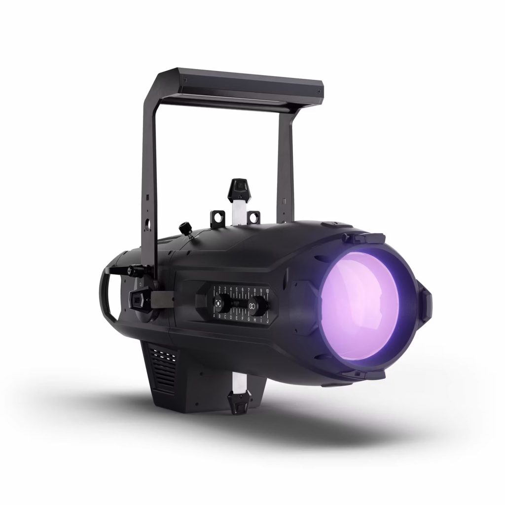
Example of a high-quality primary optic for an extended LED array using the Cameo P6 as the example
Secondary optics
The imaging plane flooded with light can now be projected using a lens.
The lensmaker’s formula is used for thin lenses: 1/f = (n-1)(1/r1 – 1/r2) = 1/g + 1/b
with
r1, r2 = radius of curvature
n = refractive index of the lens material
g = distance of object to main plane
b = distance of projected image to main plane
In addition, for anyone who wear glasses (or use visual aids), the term “dioptre” (dpt) is a familiar word. The refractive power B is provided in the unit “dioptre”. In turn, the refractive power is the quotient of the refractive index of the lens material (n) and the focal length (f), or B=n/f for short.
The following diagrams show how the imaging distance can be determined in graphic form. To do this, a beam of light is drawn from any point on the object, parallel to the optical axis, to the main plane of the lens. From this point, a line is then drawn through the focal point of the lens. Instead of the focal point line, a line is now drawn from the object through the centre of the lens. A sharply projected image is now also produced where the two lines intersect (at the intersection point). This is because the centre beam leaves the thin lens almost uninterrupted. If the lens is now moved towards the focal point, the image is enlarged at a greater distance, just as we need it for our profile spotlight.
A – imaging plane
B – projected image
C – lens
f – focal point
G – parallel beam
H – focal ray
rA – object width
rf– focal length
rB– image width
Graphical determination of the imaging distance
Border view
If we place the imaging plane at twice the distance of the focal length, the projected image will be the same size. If the object is located further away from the lens, the projected image would be made even smaller, which, of course, makes no sense for our applications.
A – imaging plane
B – projected image
C – lens
f – focal point
Imaging plane with 2f distance; projected image is the same size.
If we move the imaging plane towards the focal point, you will see that light rays in the image become more parallel over time and ultimately no longer have a point of intersection. No more image is projected.
A – imaging plane
C – lens
f – focal point
Imaging plane with f distance; no image is projected any more.
Stay tuned for more expert knowledge about stage lighting and profile spotlights! In the next part, we’ll pick up this topic and take a detailed look at tube types and zoom technologies.
This might also interest you

Palmer introduces the new MO ...
22. July 2025

Party meets precision – Ca ...
17. July 2025
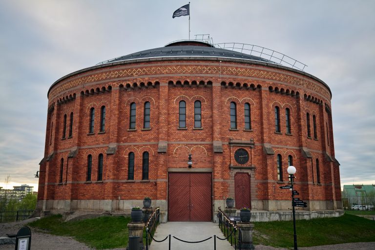
Light in the old gas tank � ...
15. July 2025
Recent Post


Popular Posts


UK Show Space – Now Open! A Recap of the Opening
January 31, 2024
